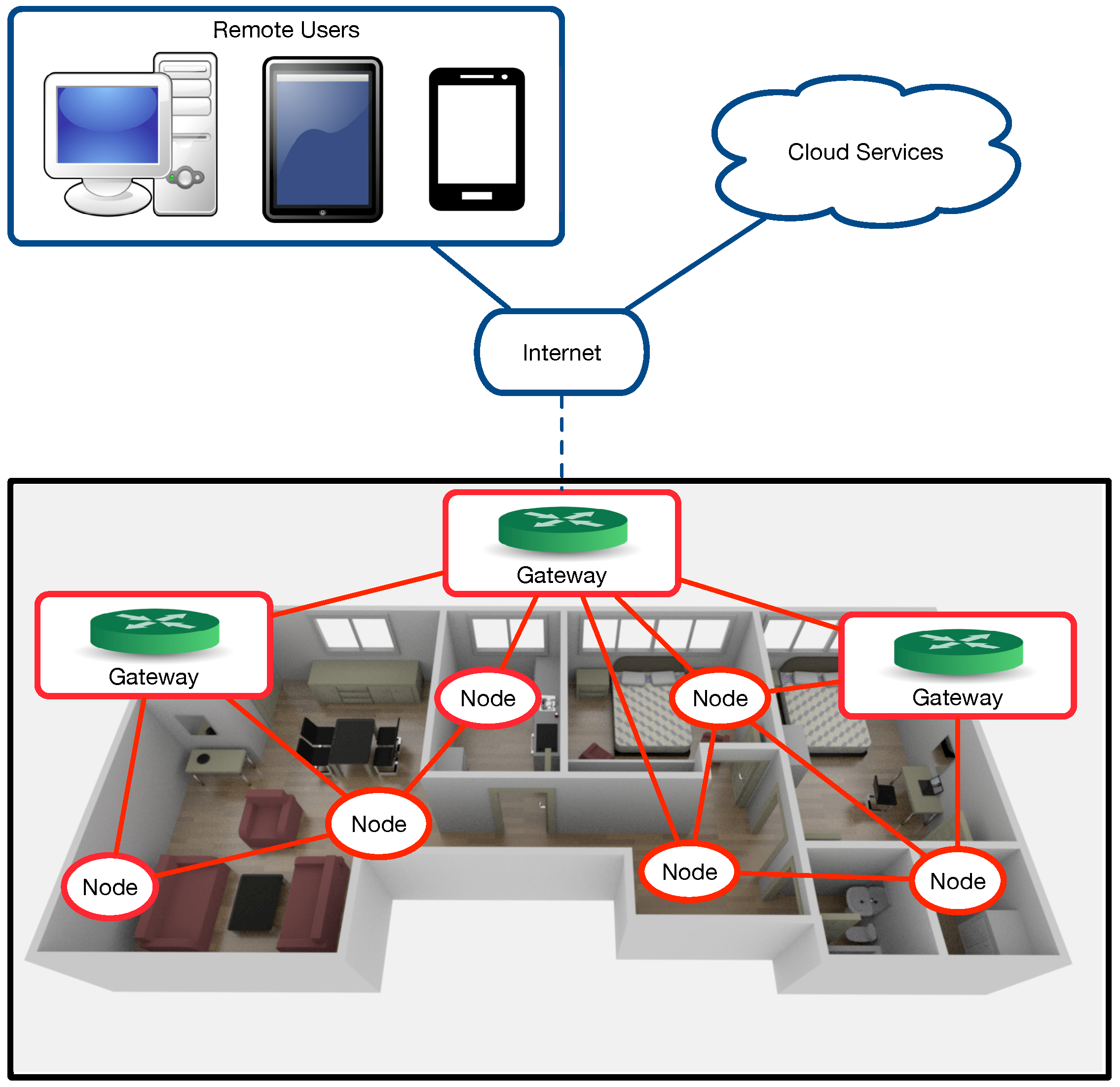
How To Build A Smart Home Sensor Circuit Diagram The Things Network allows to create applications to exchange data with your devices — often referred to as nodes as well — as shown here. In my case, my goal was to create this simple unidirectional data flow: device -> gateway -> network server -> application server. In short, I took the following steps to achieve it: I signed up on TTN
TL;DR Key Takeaways : Zigbee is a low-power, mesh networking protocol ideal for smart home and IoT applications, offering energy efficiency and independence from internet connectivity. Popular
Smart IoT Sensor Built With XIAO ESP32C6: WiFi, MQTT ... Circuit Diagram
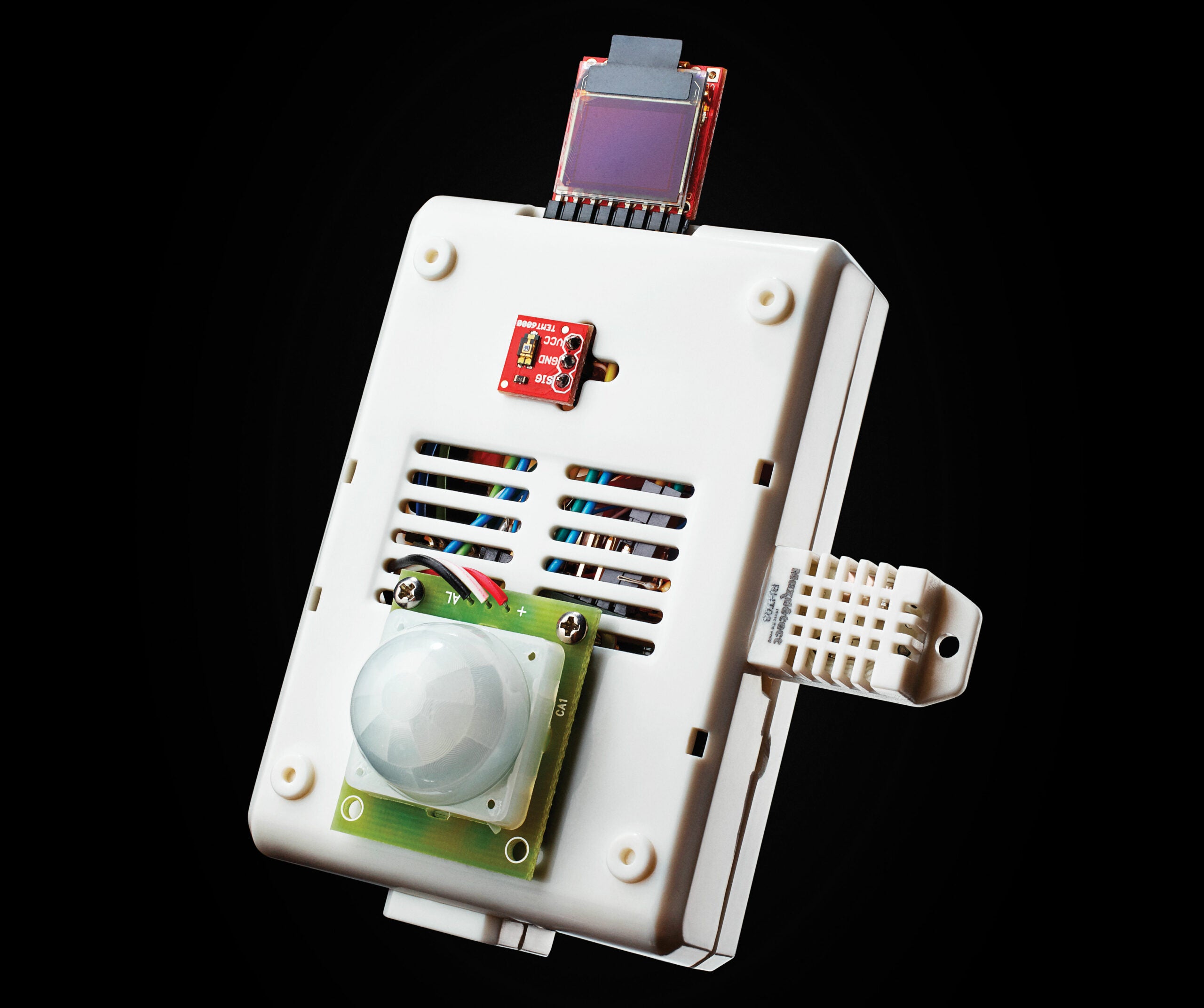
Sensor networks are no longer expensive industrial constructs. You can build a simple sensor network from easily procured, low-cost hardware. All you need are some simple sensors and a microcontroller or computer with input/output capabilities. Yes, your Arduino and Raspberry Pi are ideal platforms for building sensor networks.
A smart sensor network consists of multiple sensors that collect data from their surroundings. These sensors can measure temperature, humidity, light, motion, and more. The data collected is sent to a central system for analysis. This setup is useful in various applications, such as smart homes, industrial automation, and environmental

How to Build an IoT Sensor Tutorial Circuit Diagram
The sensor comes with a 10k ohm resistor that connects the data pin to power as a pull up resistor while another wire connects it to GPIO D3. Be careful to follow the setup below and make sure you double check the datasheet for the sensor and RF module to ensure that the components are positioned in the breadboard properly and the power, ground, and signal pins are connected to the right pins.