cost electronic stethoscope DIY Circuit Diagram The DIY Wireless Digital Stethoscope project aims to create a modern stethoscope using wireless communication and digital signal processing. This project allows for remote monitoring of heart and lung sounds, offering medical professionals an enhanced tool for diagnosis and patient care. Hello, My goal is to design electronic stethoscope (the mos simple one) and i have big problem. I was thinking about using about microphone connected to circuit with audio amplifier and on output i have headphones. It's gonna work? and could anyone give some hints how to design this circuit
For the MIC, we use the popular electret MIC, which is the recommended device for all microphone based circuit applications. For the amplifier, we use a standard IC LM386 based amplifier circuit. The entire circuit of the bluetooth stethoscope transmitter circuit is shown below: Parts List Resistors 1/4 watt 5% 4k7 = 1 100 ohm = 1 10 ohm = 1
electronic stethoscope Circuit Diagram
A medical device called a stethoscope is used to hear sounds made by the body, primarily by the heart or lungs. One of the crucial medical tools that influence remote or self-diagnosis in the medical field is the electronic stethoscope. In this video you have seen about the digital stethoscope and how to build your own digital stethoscope.And I also explained what are the components required

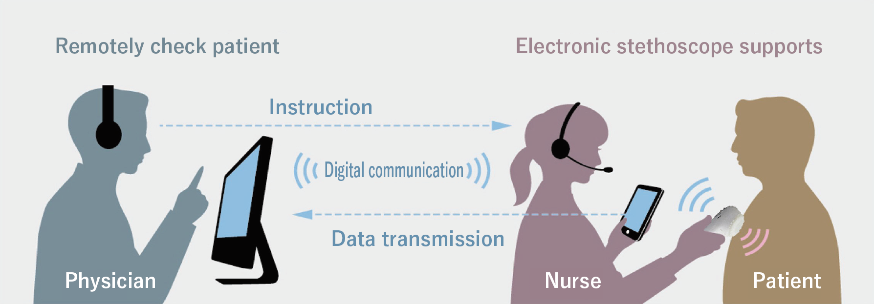
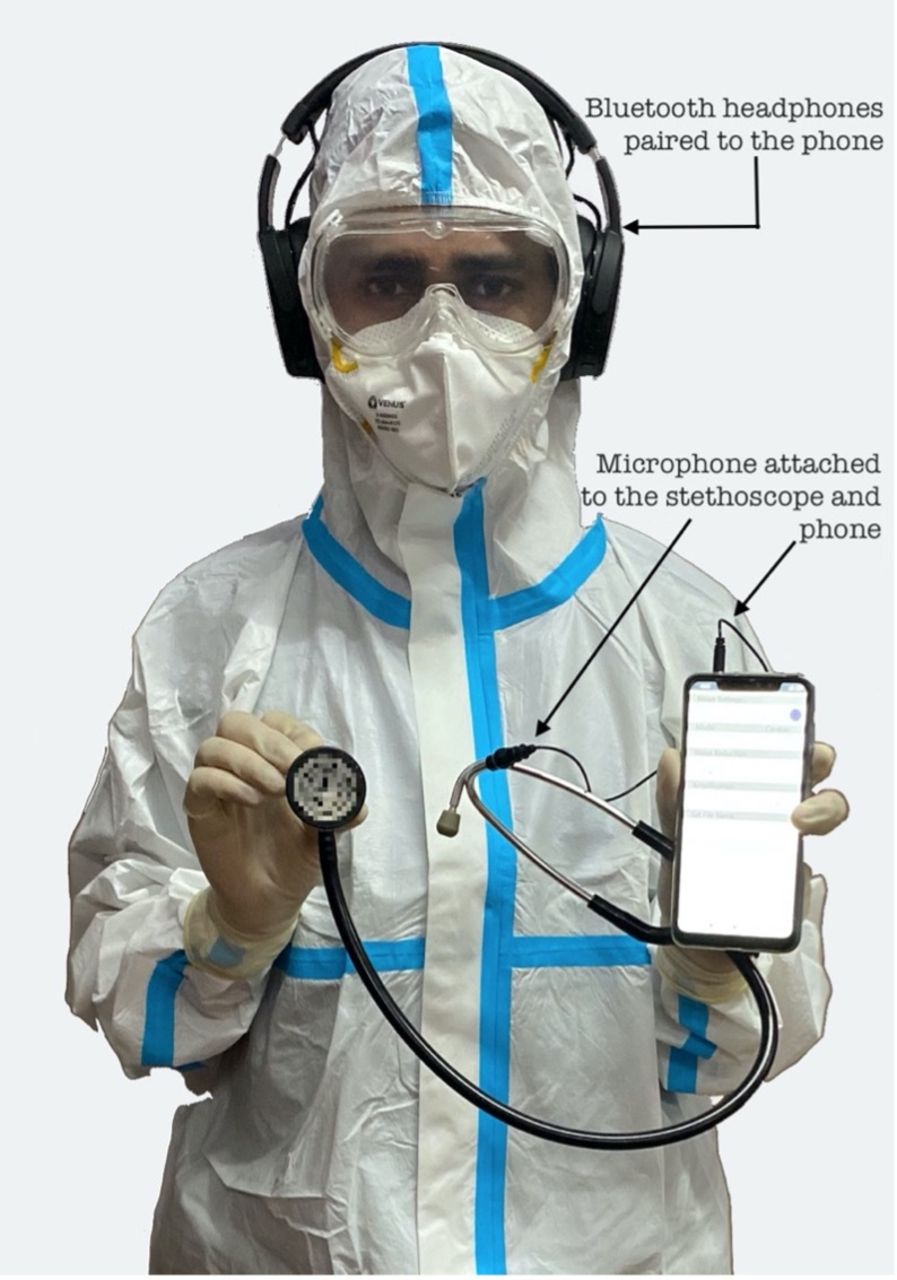
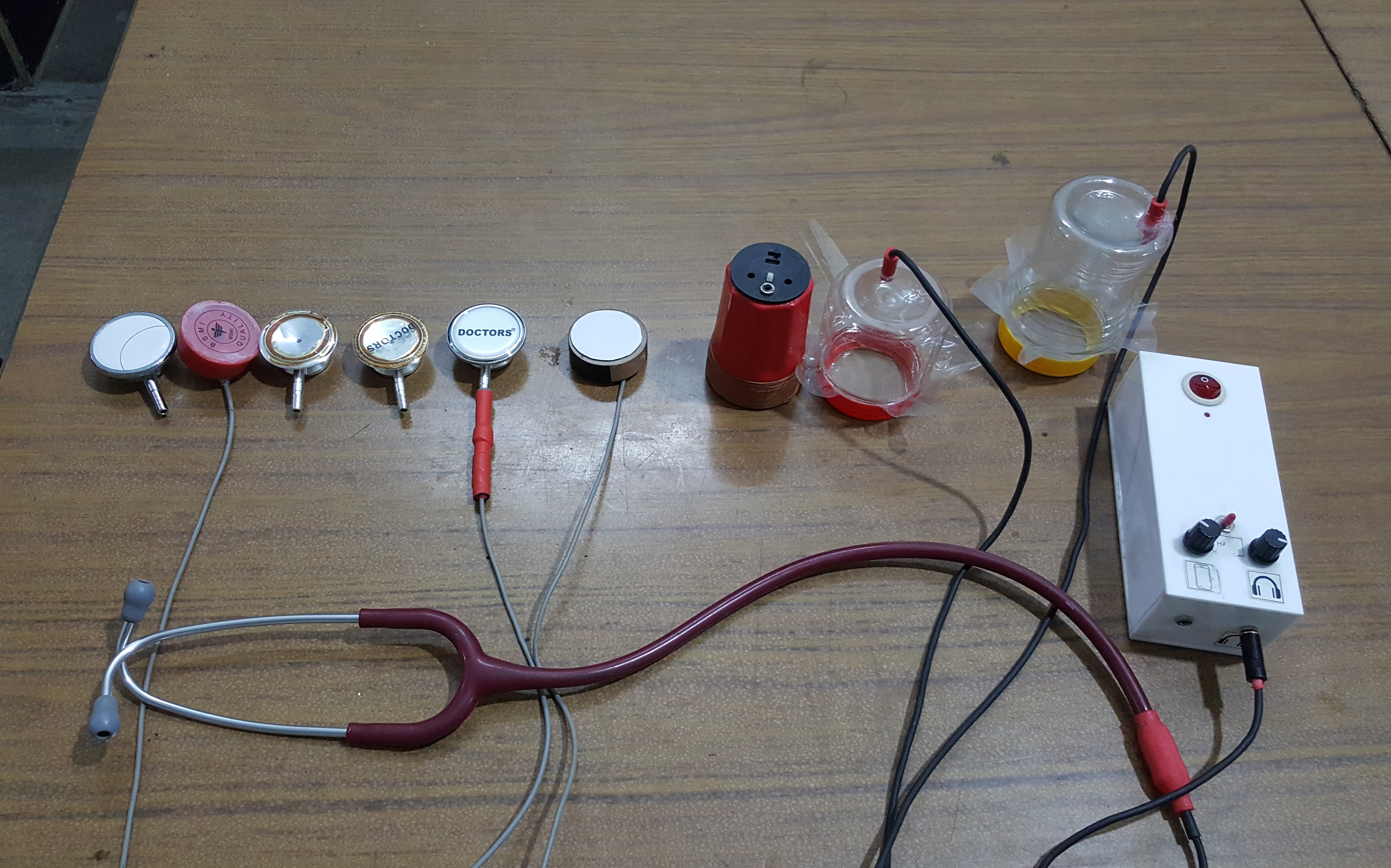
So without further ado let's get started. How Does Wireless Digital Stethoscope Work? Before we go any further in the article, let's discuss how this circuit works. In order to get the heartbeat data, we will first get a stethoscope and cut it in half to fit a condenser microphone, so that we could get the heartbeat sound from the stethoscope.
Digital Stethoscope Circuit Diagram
The purpose of this project was to design and implement a digital stethoscope to serve as a platform for potential computer aided diagnosis (CAD) applications for the detection of cardiac murmurs. The system uses a custom-built sensor to capture heart sounds at 8 kHz and converts them to electrical signals to be processed by an ATmega644 microcontroller. The captured signals are outputted via This is Electronic Stethoscope circuits.Usually the stethoscope is a medical device that listens to the heartbeat.We can make it with least amount of parts.